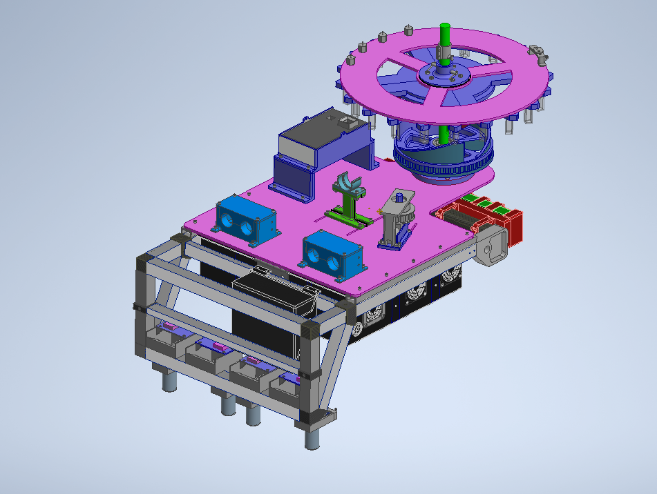
Analysis Chamber
CAD of most AstroTech systems (‘22-’23) in Autodesk Inventor
Overview
The AstroTech sub-team on the Cornell Mars Rover (CMR) Project Team oversees the creation of a life-detecting chemical testing lab on the rover for the science portion of the University Rover Challenge. During this challenge, the rover collects samples from different sites and then analyzes these samples in-situ, providing our science team with the data required to decide on the presence of life. During the 2022-2023 school year, we chose to implement an off-the-shelf spectrometer to analyze our collected soil samples. I was tasked with independently designing and integrating this system from the ground up.
The system needed to first pump the soil/chemical mixture from the mixing chamber into the cuvettes and then mix the solution with chemicals already in the cuvettes. Each cuvette needed to be inserted and removed from a tight-fit rectangular hole in the spectrometer for analysis. A digital microscope had to be mounted to view the cuvettes as they filled. No spillage or cross-site contamination was tolerated during this entire process. Finally, the system had to integrate seamlessly with the rest of the AstroTech lab and rover.
Mechanism
The system’s design is based upon three main components: a single motor belt drive, a sprag clutch, and a circular ridge profile. The sprag clutch is used to prevent the rotation of the cuvettes in one direction but allow it in the other. The cuvette carousel rides along the ridge on three 3D-printed teeth, allowing its movement to be determined by a combination of the spin direction and geometry of the ridge. The ridge is driven by a belt and a single motor.
If the motor spins in one direction, the sprag-clutch will prevent rotation of the cuvettes, causing them to follow the ridge profile in the vertical direction. This movement is what allows for a direct raising and lowering of the cuvettes into the spectrometer hole.
The second direction of motor rotation allows for the rotation of the cuvettes – a necessity to make sure every cuvette gets filled and analyzed. The ridge profile contains a small “hook” spot that catches the teeth and spins the entire system.
Limit Switches
The system’s position was extremely important because there was little to no tolerance on the hole in the spectrometer. I designed a series of limit switch mounts to provide data on all these positions. I then integrated with our Software and Electrical sub-teams to communicate the correct order of events for the system.
One limit switch measured the rotation of the cuvettes. I decided to mount this limit switch on the lid (which does not spin with the cuvettes) and have the cuvette holder trigger it to get the most accurate data. I designed an adjustable mount for a simple lever limit switch that would detect when the carousel had rotated to the next cuvette.
A second limit switch was implemented on the shaft to detect vertical motion of the carousel. Once again, I designed an adjustable mount for this to help with the testing process. It was able to trigger when the system was at its peak height, allowing us to know when the cuvettes were in the proper position for the motor to switch directions and for rotation to begin.
Cuvette Filling Process
To fill my system, a separate peristaltic pump was used to pump the samples from each of the four mixing chambers through a series of filters into the cuvettes. I mounted four flow restrictors to the lid of my system and attached those to the filtration tubes. This increased the flow rate of the samples, which allowed them to mix with the chemicals already in the cuvettes.
There were five cuvettes per site totally at twenty cuvettes that needed to be filled and analyzed during the competition. The science members required that the amount of time between the cuvettes filling and getting analyzed must be the same within each sample site for the most accurate data. To make this request a reality, I communicated a filling pattern that involved filling certain cuvettes while analyzing others to the Software and Electrical sub-teams.
Mounting Plate
The final major portion of the design involved integration with the rest of the rover, specifically the Drives sub-team and their frame design. For the science portion of the competition, we decided to remove the rover’s arm to allow for more room for the carousel, which took up quite a bit of room. I was able to use the strong arm base to mount my carousel, which removed a lot of unwanted jostling of the system. I chose to use a polycarbonate plate to mount everything for my system on. This plate was then mounted on u-channel spacers on top of the rover’s E-core (electrical core).
The polycarbonate was more rigid than acrylic and was easy to machine (we just had it water jetted). I decided to mount everything to a plate first because it allowed for more exact positioning of the pieces of the analysis system such as the motor, carousel, pumps, and digital microscope. Using a plate also decreased the mounting time of everything by a lot, significantly improving the testability and operability.
The motor was mounted on slots to allow the belt to be tensioned properly. The pumps were enclosed in 3D-printed cases to remove the risk of leakage. The digital microscope was also mounted on slots to allow the focus to be changed depending on our needs. Overall, it was a good call to consolidate all the pieces of this system onto one plate and would’ve been much harder to integrate had they mounted directly to the frame.
